Benefits of Zone Cabling Architecture over Conventional Cabling
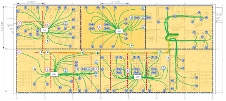
Zone cabling is a network infrastructure methodology that enables workspaces to be more flexible and easily adaptable than with a standard structured cabling architecture. In addition, zone cabling provides a systematic setup for managing hundreds of devices over a single network. For this reason it is the ideal solution for smart building connectivity. However even in buildings with limited smart functionality, the cost and efficiency benefits can be significant.
Zone cabling architectures must be carefully planned and there are a number of factors to be considered. In this example we will look at a simplified zone cabling requirement and see how adding all a number of different types of applications will impact the overall cabling design.
There are many types of application that might be included in a cabling network – including lighting, voice data, wireless, video surveillance, AC, HVAC, access control, AV, energy management and many more. However we will keep our list to a minimum in order to keep the design relatively simple.
Wiring an office floor using conventional methods
In this example we will calculate the wiring required for a typical office floor which includes office workstations, audio-visual equipment, security cameras, temperature sensors, card readers, and an intelligent lighting system.
Work Area Outlets
The first thing to consider is the number of work area outlets (WAOs) we will need.
First, look at where people will be sitting and therefore where a WAO will be needed. In this example there are 8 main areas where people will be sitting with a total area 490m² / 5274ft². There are a minimum of 49 work areas of 10m², which means a minimum of 98 WAOs –2 WAOs per work area.
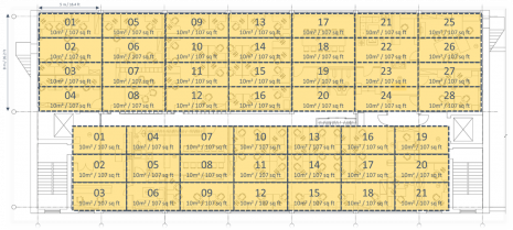
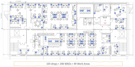
Having positioned our WAOs, giving us 103 drops for 206 WAOs. These are telecommunications outlets (TOs) as they are connecting a voice or data service.
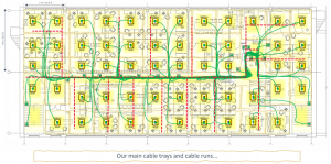
From the telecoms rooms we can now visualize our cable trays and main cable runs.
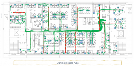
This gives us 5,396m (17,698ft) of cable – an average of 26m / 86ft per WAO with the longest permanent length of 44m / 144ft.
Wireless Access Points
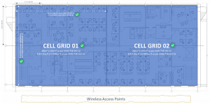
Positioning of Wireless Access Points (WAPs) should refer to ANSI/TSB guidelines and adjust to the size of the floor. Remember the first step in a wireless LAN deployment is to begin with a site survey to assess the radio frequency behavior in a specific environment. Many issues can arise due to insufficient planning or site surveys performed poorly. The grid may be made smaller to support higher data rates or occupancy.
>Essential Guide to SCS Standards
In our example a minimum of 2 grids is required, but we will install 4 WAPs to ensure the network can support changes in use. Cat 6a cabling is deployed to each WAP for increased data rates and power delivery.
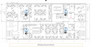
Our cables follow our main cables for a total of 163m / 535 ft.
AV Equipment outlets
Next we will position the audio-visual (AV) equipment outlets. In this design there are a total of 8 WAOs which can be used for AV applications in these 2 meeting rooms.
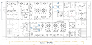
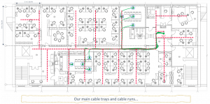
Again, the cables follow the main cable trays for 402m / 1,319ft of cable.
IP Cameras
Now we shall add equipment outlets to connect IP cameras. We could also have used MPTL connectors for these cameras.
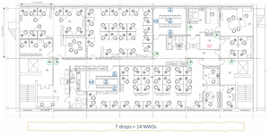
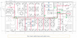
These are called Service outlets (ISO IEC) / Equipment outlets (ANSI/TIA) since they are connecting to a building device.
Other equipment
In this example we shall add card readers and temperature sensors as follows:
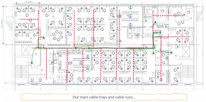
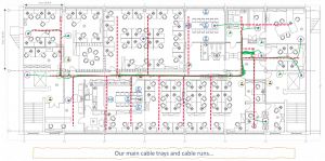
In total this adds 878m / 2,828 ft of cable.
Lighting
Lighting is an important consideration for employee wellbeing and productivity and must be preceded by a comprehensive site survey.
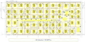
There are multiple options to attach intelligent luminaires to an ethernet network. For the sake of simplicity we will consider one MPTL plug per luminaire.
Summary: Conventional cabling
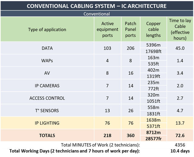
For this conventional cabling installation we would need 8,712m / 28,577ft cable, which works out at 10.4 days of work.
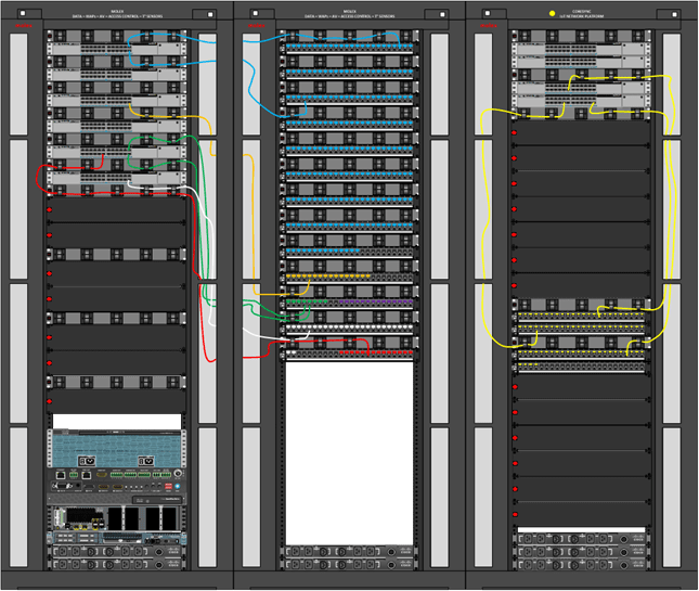
Below is the summary of the requirements of the cabling system for this office floor using conventional cabling. In this example we have only considered the installation of the cabling – we have not considered the termination of the patch panels, WAOs or MPTL plugs because there would be no difference between conventional cabling and zone cabling.
Wiring the office using a Zone cabling system
Cabling architecture can be centralized or decentralized, active or passive.
Active zone cabling greatly reduces the amount of copper cabling since each zone enclosure may be attached to the TR with fiber optic cable. For this example we are using a decentralized fixture-centric approach. This means the majority of active equipment and network switches will be decentralized.
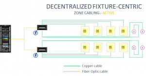
In this design we will also use MPTL plugs for our lighting troffers.
Let’s look at the first zone enclosure, ZE1, in detail. The other zones will follow the same basic pattern.
Zone Enclosure 1
We will have to fit 20 WAOs, 2 temperature sensors, 1 card reader and 1 WAP. Each will have double cable runs, so 48 runs are needed. For lighting 12 additional cable runs are required.
ZE1 will be connected to the TR with a 6-core fiber optic link. All remaining endpoints will be distributed with cat 6a cable runs.
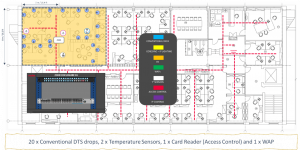
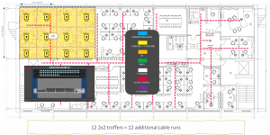
Some substantial differences between zone cabling and conventional cabling are already evident. The length of copper cabling required has been greatly reduced – by 69%.
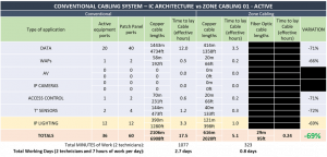
For each subsequent zone 1-4, the active zone cabling requirements have also been calculated. The final WAOs and devices are located near to the TR so there is no need for separate zone enclosures – they can all be connected directly to the TR.
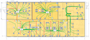
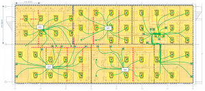
For zone 2 we estimate a saving of 870m/ 2,851ft of cable – a reduction of 55%.
For zone 3 we estimate a saving of 1552m / 5,089ft of cable – a reduction of 65%.
For zone 4 we estimate a saving of 830m / 2,725ft – a reduction of 53%.
The final comparison
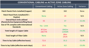
Total cable length overall = 8,712m/28,577ft vs 4,031m / 13,221ft = 53.7%
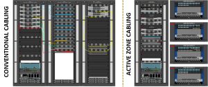

The zone cabling system has required 89m of fiber optic cabling and 24 fiber optic patch panels, where the conventional system only used copper cables.
However, even given this, the zone cabling system required 53.7% less cabling overall.
There are also substantial savings in terms of time to install, reducing the cost of manpower and the amount of disruption to work areas.
Molex zone cabling solutions
The ability to rapidly reorganize workspaces starts with a dynamic network architecture. Molex’s zone cabling solution introduces a new dimension of flexibility to organizational facilities with easy connection and reconnection of devices and hardware, from desktop computers to smart building systems and IoT devices.
Technical webinars
This example was explained in more detail in a webinar presented by our Global Pre & Post Technical Sales Manager, Christophe Hinet RCDD. For access to our webinars, register for a free account on our Customer Support Portal or contact your local Molex sales representative.
Technical document: Essential guide to structured cabling solutions standards
Zone cabling: Frequently Asked Questions guide can be downloaded from the Customer Support Portal. Log in or apply for access here.
